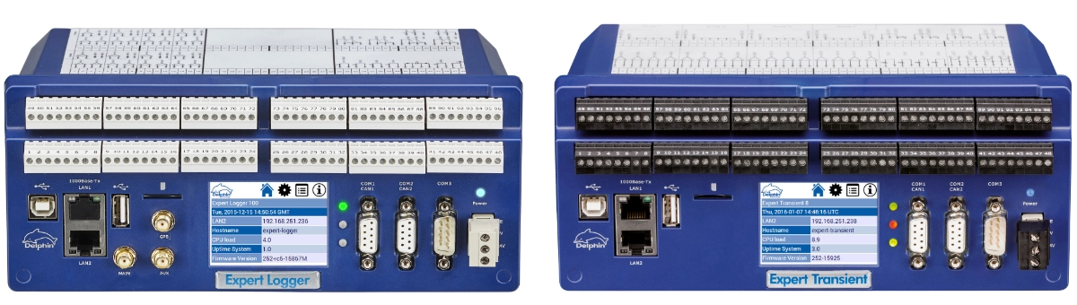
Expert Series Professional Data Logger & Data Acquisition System
| Models | EXPERT LOGGER 100 | EXPERT LOGGER 200 | EXPERT LOGGER 300 | EXPERT LOGGER 400 |
|---|---|---|---|---|
| Product Images |  |
|
|
|
| Number of Analog Input Channels | 16 Channels | 32 Channels | 46 Channels | 16 Channels |
|---|---|---|---|---|
| Analog Input Types | Pt100, Thermocouple, 0/4-20 mA, ±20 mA 0-5 VDC, 0-10 VDC, ±10 VDC mV/V, Load Cell, LVDT, pH Probe |
Pt100, Thermocouple, 0/4-20 mA, ±20 mA 0-5 VDC, 0-10 VDC, ±10 VDC |
Pt100, Thermocouple, 0/4-20 mA, ±20 mA 0-5 VDC, 0-10 VDC, ±10 VDC mV/V, Load Cell, LVDT, pH Probe |
|
| Analog Channel Resolution | 24 Bit - High Accuracy | |||
| Isolation Between Analog Channels and Power Supply | Available | |||
| Analog Channel Sampling Rate (Total) | 1,000 measurements/second | 2,000 measurements/second | 3,000 measurements/second | 1,000 measurements/second |
| Number of Digital Input Channels | 4 Channels | 4 Channels | 0 Channels | 1 Channel |
|---|---|---|---|---|
| Digital Input Types |
Logic 0/1 or Pulse/Frequency |
Logic 0/1 or Pulse/Frequency |
-- |
Logic 0/1 or Pulse/Frequency |
| Input Voltage |
Logic 0: 0-1 VDC ±400 VDC Galvanically Isolated |
Logic 0: 0-1 VDC ±400 VDC Galvanically Isolated |
-- |
Logic 0: 0-1 VDC ±400 VDC Galvanically Isolated |
| Number of Digital Outputs | 4 Channels | 4 Channels | 0 | 0 |
| Maximum Switching Ratings | 50 V / 2.5 A for 2 seconds 250 mA continuous |
50 V / 2.5 A for 2 seconds 250 mA continuous |
-- | -- |
| PWM Function |
Available 5 Hz...10 kHz 1:1000 |
Available 5 Hz...10 kHz 1:1000 |
-- | -- |
| Channels Configurable as Digital Inputs or Outputs | 4 Channels | 4 Channels | 1 Channel | 24 Channels |
| Input Voltage |
Logic 0: 0-1 VDC ±400 VDC Galvanically Isolated |
Logic 0: 0-1 VDC ±400 VDC Galvanically Isolated |
Logic 0: 0-1 VDC ±400 VDC Galvanically Isolated |
Logic 0: 0-1 VDC ±400 VDC Galvanically Isolated |
| COM Ports |
2 x RS-485 1 x RS-232 |
|||
|---|---|---|---|---|
| SDI-12 Meteorological Protocol |
1 |
1 |
-- |
-- |
| Ethernet |
1 x Ethernet Communication with Delphin software |
|||
| USB | 1 x USB For PC connection |
|||
| Memory Capacity | 14 GB Internal Memory (420 million recorded measurements) | |||
|---|---|---|---|---|
| Calculation Channels (Mathematical Operations) |
You can create formulas using all channels received by the Expert Logger through analog, digital or communication protocol inputs, display the calculation result in real time as a separate channel, record it like any other channel and include it in reports together with other measured values. |
|---|---|
| Counter | You can perform counting operations on data received from digital or analog channels. For example, you can easily define a calculation for the total amount of water that has passed. The counting operation can also be reset. |
| Linearization | You can apply linearization with an unlimited number of points to all measured or calculated parameters. This function can be used for sensor error correction, comparison or conversion to another parameter. |
| Operating Time | This function allows you to count time in different time units and trigger other operations when predefined values are reached. Time-based calculations such as machine operating time, downtime and alarm duration can be performed. |
| Statistics | This function allows you to obtain statistical data such as minimum, maximum, variation and standard deviation. |
| Logic Gates | This function allows you to process digital data, such as DI signals or alarms, using AND, OR, NOT and other logic gate functions. |
| Limit (Alarm) Channel | This function allows you to define alarm setpoints and trigger other channels or operations when the specified conditions occur. |
| Control Function | Expert Logger can also be used as an advanced controller when required. It features an advanced PID control function and Auto Tune capability. |
| Pulse Generator | You can generate square-wave signals with adjustable duration and frequency and use these outputs in other formulas. |
| Other | This table lists the main functions. Expert Logger provides at least twice as many additional selectable functions beyond those shown here. |
| Models | Expert Transient 4 | Expert Transient 8 | Expert Transient 12 | Expert Transient 16 |
|---|---|---|---|---|
| Product Images |  |
|
|
|
| Number of Analog Input Channels | 4 Channels | 8 Channels | 12 Channels | 16 Channels |
|---|---|---|---|---|
| Analog Input Types |
4...20 mA 0...10 VDC -25....+25 VDC |
|||
| Analog Channel Resolution | 24 Bit High Accuracy |
|||
| Isolation | Channel-to-Channel Isolation | |||
| Analog Channel Sampling Rate (Per Channel) | 50,000 measurements/second per channel (50 kHz) |
|||
| Number of Digital Input (DI) Channels | 4 Channels | 4 Channels | 4 Channels | 4 Channels |
|---|---|---|---|---|
| DI Signal Level | Low (Logic 0): 0 .. 1 VDC High (Logic 1): 5 .. 100 VDC @3.5 mA |
Low (Logic 0): 0 .. 1 VDC High (Logic 1): 5 .. 100 VDC @3.5 mA |
Low (Logic 0): 0 .. 1 VDC High (Logic 1): 5 .. 100 VDC @3.5 mA |
Low (Logic 0): 0 .. 1 VDC High (Logic 1): 5 .. 100 VDC @3.5 mA |
| DI Frequency |
1 MHz |
1 MHz |
1 MHz |
1 MHz |
| Digital Input Isolation | 400 VDC between channels and between channels and system power supply |
|||
| Digital Output (DO) Channels | 8 Channels | 8 Channels | 8 Channels | 8 Channels |
| PWM Function |
Available 5 Hz...10 kHz |
|||
| DO Switching Specifications | 250 mA | |||
| Number of Analog Output (AO) Channels | 4 Channels | 4 Channels | 4 Channels | 4 Channels |
|---|---|---|---|---|
| Resolution | 16 Bit | |||
| Output Options |
0-20 mA, 4-20 mA, 0-10 VDC, -20...+20 mA, -10...+10 VDC |
|||
| Analog Output Isolation | 400 VDC between channels and between channels and system power supply |
|||
| COM Ports |
2 x RS-485 1 x RS-232 |
|||
|---|---|---|---|---|
| SDI-12 Meteorological Protocol |
1 |
1 |
-- |
-- |
| Ethernet |
1 x Ethernet Communication with Delphin software |
|||
| USB | 1 x USB For PC connection |
|||
| Memory Capacity | 14 GB Internal Memory (420 million recorded measurements) | |||
|---|---|---|---|---|
| Calculation Channels (Mathematical Operations) |
You can create formulas using any channels received by the Expert Logger through analog, digital or protocol-based inputs, display the calculation result in real time as a separate channel, record it like any other channel and include it in reports together with the measured values. |
|---|---|
| Counter | You can perform counting operations on data received from digital or analog channels. For example, you can easily define calculations such as total accumulated water flow. The counter can also be reset when required. |
| Linearization | You can apply multi-point linearization to any measured or calculated parameter with an unlimited number of points. This function can be used for sensor error correction, comparison or conversion to another parameter. |
| Operating Time | This function allows you to count time in different time units and trigger other operations when predefined values are reached. It can be used for applications such as machine operating time, downtime or alarm duration monitoring. |
| Statistics | This function allows you to obtain statistical values such as minimum, maximum, variation and standard deviation. |
| Logic Gates | This function allows you to process digital data such as DI signals or alarms using AND, OR, NOT and other logic gate functions. |
| Limit (Alarm) Channel | This function allows you to define alarm setpoints and trigger other channels or operations when the specified conditions occur. |
| Control Function | Expert Logger can also be used as an advanced controller when required. It features an advanced PID control function and Auto Tune capability. |
| Pulse Generator | You can generate square-wave signals with adjustable duration and frequency and use these outputs in other formulas. |
| Other | This table lists the main functions. Expert Logger provides at least twice as many additional selectable functions beyond those shown here. |